Module Replacement
SCR AND SSR MODULE REPLACEMENT INSTRUCTIONS
- Disconnect power from the controller containing the SCR module that is to be replaced.
- Remove electrical connections, making notes or sketches for easy reassembly.
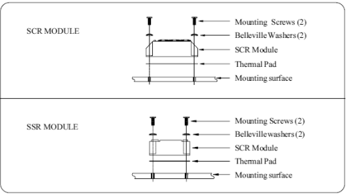
- Remove the SCR module from the mounting surface. Be sure to retain all screws and mounting hardware.
- With a clean, dry cloth or paper towel, remove as much of the thermal compound as possible from the surface where the replacement module is to be positioned. Make sure that there is no dirt or thermal compound remaining on the mounting surface.
- Remove the brown shipping paper from the Thermstrate® thermal pad. Place the thermal pad on the surface beneath the SCR module. This pad is a thin, soft aluminum foil with a layer of thermal wax on both sides. The purpose of this pad is to fill the tiny cavities on the surfaces to improve thermal conductivity to the heatsink.
- Screw the SCR module to the mounting surface. Use the "Belleville" spring washers "dome" up, to ensure a constant mounting force. Tighten the screws evenly, applying as much torque as possible without damaging the threads.
- Reattach the electrical connections to the SCR module.

Hockey Puck SCR Replacement
IMPORTANT: It is recommended that replacement of hockey puck SCRs be done at the factory due to critical installation requirements. This procedure requires the disassembly of electrical wiring and structural components in the controller. Use care and keep track of everything you do for reassembly.
- It is recommended that you keep notes and make drawings of all steps as you disassemble the controller.
- Save all hardware as you take it off.
- Clean contact surfaces. Apply thin coat of anti-oxidant paste to SCR contact areas.
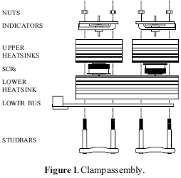
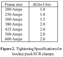
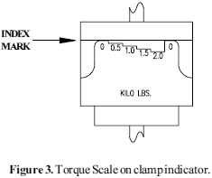
- Reassemble heatsink - SCR - clamp assembly. (See figure 1.) Tighten to pressure recommended in figure 2.
- Clean contact surfaces in areas where heatsink, buses and straps come together. Apply thin coat of anti-oxidant paste to mating surfaces.
- Reassemble heatsinks, buses and straps.
- Reassemble controller in reverse order of dissassembly and reinstall it.
- Apply power and command signal.
- Refer to troubleshooting portion of instruction manual if problems occur.


