SCR Design Engineering Checklist
 Our engineers have released a new Design Checklist to help our customers design efficiently with SCR Power Controllers.
Download the complete checklist here: Control Concepts SCR Design Checklist.PDF
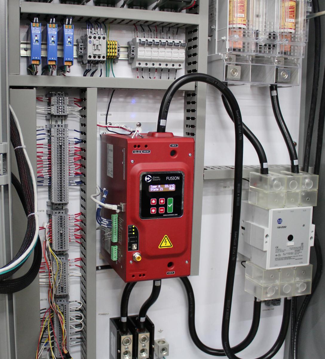
Designing with SCR Power Controllers - Part 1: Design and Installation
Use mechanical safety disconnects for feeder circuits
A contactor, circuit breaker, or mechanical disconnect should be used ahead of the fusing and SCR power controller to serve as a mechanical safety disconnect. Outputs of SCR power controllers are live whenever voltage is present on the controller inputs!
Verify orientation for natural convection cooled power controllers.
Passively cooled SCR power controllers rely on natural convection. The controller needs to be oriented so the cooling fins run vertical in order to dissipate the rated heat properly. Failure to do so will shorten the life of the SCR and may cause an unintended system shutdown.
Keep contactors upstream of an SCR
Always keep contactors upstream of the SCR power controller to prevent damaging voltage kickback during opening of the contacts.
Size current of power controllers and load for the lowest voltage your facility may see.
Dips in facility power may cause your power controller to run at a higher current output than planned in order to achieve the desired power output. This may also lead to extra heat load within the electrical enclosure.
Understand certification requirements at your customer’s location.
Check with your customer to verify local code requirements before planning your electrical panel. If the final destination is within the US, pay special attention to Short Circuit Current Rating (SCCR) and available fault current at the facility. SCR power controllers require specific design considerations in order to meet SCCR requirements in the panel.
Protect the controller from dust, metal shavings, or screws
During system installation, small metal shavings can drop into the top of the controllers. This may cause short circuits or arcing. Cover the unit or wait to mount controllers until holes have already been drilled in the enclosure.
Check system thoroughly after installation and mounting
Make sure all lugs are torqued to proper torque specifications. Inspect for frayed wires. Follow recommended strip length for terminals.
Test all system fault and recovery scenarios during startup
Verify system design is capable of handling and recovering from all fault scenarios:
- Over current trip
- Communications failure
- Over temperature
- Shorted SCR
- Phase lock
- Phase loss (3 Phase)
- Load imbalance (3 Phase)
- Limits: voltage, current, or power