SCR Controller Description
Download our guide to SCR Controllers: What You Should Know About SCR Controllers
Basically, an SCR power controller consists of the following:
- semiconductor power devices (SCR's and Diodes)
- a control circuit normally referred to as the firing circuit
- a means to dissipate the heat generated from the semiconductor devices
- protective circuits (fuses and transient suppressors).
- Timing. It is imperative, particularly in applications involving inductive loads such as transformers, that no DC be applied to the load. DC components in secondary circuits can also cause supply transformers to over heat. This requires that the ON time of the back-to-back SCR's be exactly equal. Modern circuits use sophisticated digital phase lock loop techniques which are immune to the electrical noise and varying voltages that are often found in industrial environments.
- Electrical Isolation. The command signal must be isolated from the supply and load voltage. Plus, excellent isolation is required between the circuits controlling the signals to the gates of the SCR's to prevent false turn-on of the SCR's.

The SCR
The heart of the SCR power controller is the SCR (silicon controlled rectifier, also sometimes referred to as a thyristor).
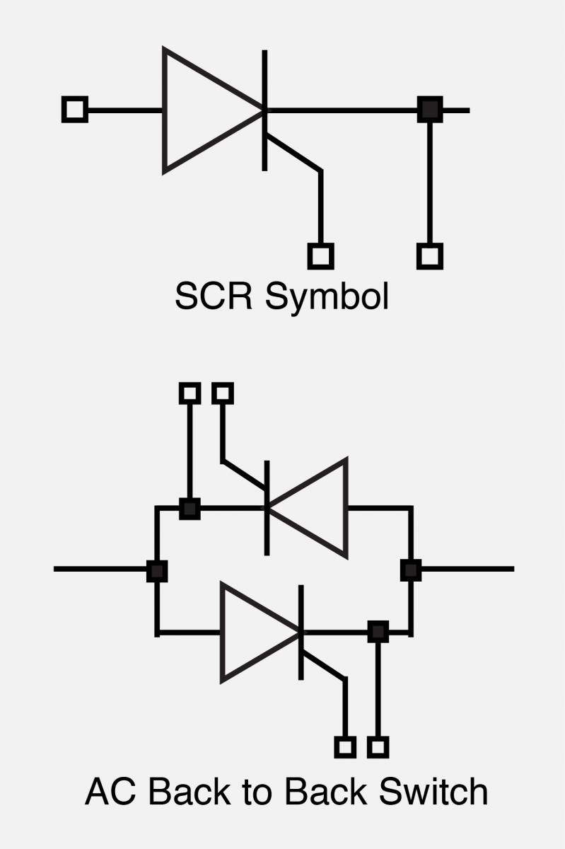
The SCR has two states, ON or OFF, and it allows current to flow in only one direction.
SCR's can remain in the off state even though the applied potential may be several thousand volts. In the on state, they can pass several thousand amperes. When a small signal is applied between the gate and cathode terminals, the SCR will begin conducting within 3 microseconds. Once turned on, it will remain on until the current through it is reduced to a very low value, called the holding current.
Because the SCR allows current to flow in only one direction, two SCR's are connected in an inverse parallel configuration to control AC current.
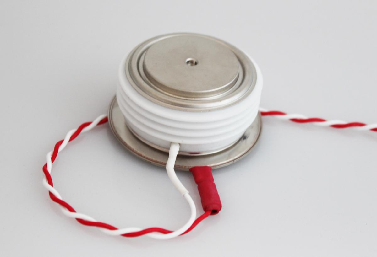
Three SCR construction styles are available: the disc (a.k.a. hockey puck), the module, and the stud mount.
Modern SCR controllers generally use hockey puck or module construction.

Hockey Puck SCR Controller Design:
The hockey puck style is an assembly that has essentially the same physical shape as a hockey puck. The construction provides excellent cooling of the semiconductor material and is generally used in higher current applications.
Module:
SCR modules are assemblies in which the SCR's are contained in a plastic enclosure with an electrically isolated mounting plate. SCR modules are becoming increasingly popular and modules containing a variety of SCR configurations are available. They are easy and inexpensive to mount to a heatsink, they typically have large surge current ratings and they provide electrical isolation, allowing multiple modules to be mounted on a common heat sink.
Electronic Circuit
The electronic circuit controls the operation of the SCR's such that the desired energy applied to the load is proportional to the command signal.
Important tasks of the circuit include:
Heatsink Requirements
- SCR's emit about 1.5 watt's of energy in the form of heat, per ampere conducted. Failure to dissipate this energy is perhaps one of the main sources of SCR failure. The reliability of SCR's decreases about 50% for every 10°C increase of semiconductor temperature. Other critical parameters such as the dv/dt rating and the blocking voltage rating also decrease rapidly with temperature.
- The heat generated by the SCR must be dissipated, thus, all controllers have some means to cool the SCR's. Typically an aluminum heatsink, with fins to increase the surface area, is used to dissipate this energy to air. Controllers with relatively small current capacities rely on natural convection. Higher current capacity controllers use a fan to force air past the fins in order to increase heat dissipation.
- Occasionally, water cooled heatsinks are used on SCR controllers with very high current ratings.